
Different shale distributions in low resistivity log response.
First, we are able to begin with a small creation approximately the resistivity logs

Resistivity log
Technique : produce a current in the adjacent formation and measure the response of the formation to that current.
Resistivity logs are used to:
? Decide hydrocarbon-bearing as opposed to water bearing zones
? Suggest permeable zones
? Determine porosity
By far the most important use of resistivity logs is the determination of hydrocarbon-bearing versus water-bearing zones. Because the rock’s matrix or grains are non-conductive and any hydrocarbons in the pores are also non-conductive, the ability of the rock to transmit a current is almost entirely a function of water in the pores. As the hydrocarbon saturation of the pores increases (as the water saturation decreases), the formation’s resistivity increases. As the salinity of the water in the pores decreases , the rock’s resistivity also increases.
Resistivity tools principle : there are two types of resistivity tool , The dual lateral log ( DLL ) and the induction log ( DIL ) both types measures the resistivity in three zones simultaneously.
LLD looks deep into reservoir
LLS Looks shallow into the reservoir
MSFL reads the resistivity close to the wellbore.

Low Resistivity response :
High deep resistivity means : HCs or Tight streak { low porosity }
Low deep resistivity means : Shale or wet sand.
Shale: Shale is defined as a fine-grained, indurated detrital sedimentary rock formed by the consolidation (by compression or cementation) of clay, silt, or mud.
It is characterized through a finely stratified structure of laminae starting from 0.1 to 0.4 mm thick. Shale carries an considerable content of clay minerals or derivatives from clay minerals, with a excessive content of detrital quartz; containing at the least 50% silt, with 35% clay or mica fraction, and 15% chemical or authigenic substances
In petrophysical analysis, shale quantity is one of the key answers used later to accurate porosity and water saturation for the results of clay bound water, (CBW).
Shale distribution in shaly sand :
Shale can be distributed in several different ways, as shown below.

Laminated shale is a unique case in petrophysical evaluation. Standard fashions for porosity and saturation do now not paintings.
Dispersed shale is usually composed of from clay minerals that shape in region after deposition due to chemical reactions among the rock minerals and the chemicals within the formation water.
Structural shale is normally deposited as particles, grains, or clasts in the course of the initial depositional segment. For instance, the flooding of a river valley can deliver dust or shale from surrounding areas.
Different shale distributions have different effect on the sand reservoir.
In a sand reservoir contain structure shale : it will affect the reservoir porosity
In a sand reservoir comprise laminae shale : it'll have an effect on best the net pay of the reservoir
In a sand reservoir contain : it will affect the porosity and permeability of the reservoir and also it will lead to a shortcut in the resistivity log response , which may result in a miss lead in the interpretation of the reservoir porosity and saturation , it could be interpreted as sand bearing water instead of a sand contain dispersed shale.
So, the question here is how to distinguish among them and to keep away from this wrong interpretation ?!
Let?S anticipate that you have a a hundred% easy sand reservoir. So the full porosity of this reservoir is 30% and the sand grains will represent 70% of the quantity of the reservoir
Hint : Porosity of sandstone is 30 % and porosity of shale is 10%
Case 1 :
In the case of the presence of structure shale ,
So in this case shale grains will update sand grains ( extent of 70% ) , the shale will convey its 10% porosity with it.
In other words , The porosity may be stronger by 10% inside the quantity of 70% of the sand
So , the porosity will increase via 70/10 and the entire porosity can be = 37 %

Case 2 :
In the case of the presence of laminae shale , in this case shale will replace the whole reservoir ( 100 & ) and also will bring its own 10% porosity.

In other words , the porosity will be reduced from 30% to 10%
Case 3 :
In the case of the presence of dispersed shale , in this case shale we will replace the porosity volume it self ( 30 % ) and as usual it will bring its own porosity.
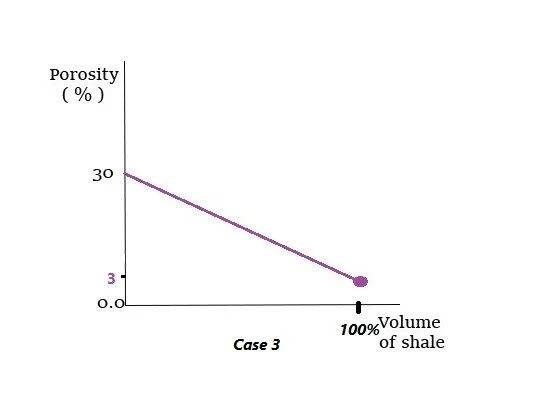
In other words , the porosity will be reduced into 3% ( 30 / 10 )Summarized figure for the differentshale distributions inshaly sand reservoir and it’s effect on the reservoir porosity.
 |
| Shale distribution model proposed by Thomas and Stieber (Tyagi et al. 2009). Here Vshale is the volume of shale, φtotal is the total porosity, φmax is the maximum porosity, and φsh is the porosity in shale |
Conclusion :
Photo Credits: Ahmed Adel
Originally blog is written by Ahmed Adel


